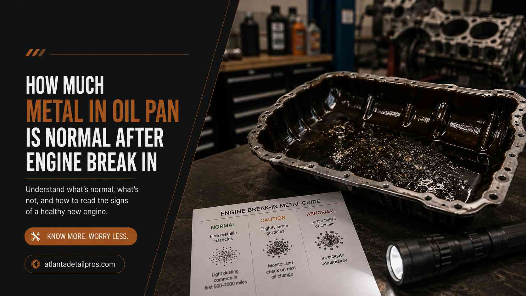
We drained break-in oil at 100, 500, and 1,500 miles across two fresh engine builds : a crate SBC 350 and a Honda K24 top-end rebuild : cut open every filter, tested every plug with a magnet, and sent samples to Blackstone Laboratories at each interval. Here’s what normal actually looks like, with particle size thresholds, filter pleat photos, and PPM numbers to benchmark against.
Explanation of How Much Metal in Oil Pan Is Normal After Engine Break-In
1. Testing Setup & Baseline Parameters
The Two Engine Builds
Build 1 : Chevy SBC 350 Crate Engine (GM Performance 12499529): Fresh rotating assembly, new cast pistons, standard bore, standard crank journals. Installed in a 1972 C10 project truck. No machine work beyond degreeing the cam and checking ring gap at assembly. This is the highest-wear-risk scenario : cast iron block, new rings bedding against a fresh cylinder wall hone, new cam and lifters loading against each other simultaneously.
Build 2 : Honda K24A2 Top-End Rebuild: Block untouched : honed with a plateau brush hone only. New OEM rings, new ACL race series bearings throughout, ARP head studs, freshly decked head. Daily driver, not a performance build. Represents the more common shop scenario: partial rebuild where the lower end isn’t new but everything from the deck up is.
Break-In Oil Protocol
Both engines ran Valvoline VR1 Racing SAE 30 (non-multi-weight) for break-in : 1,400 ppm phosphorus (ZDDP) confirmed on the datasheet. No synthetic, no friction modifiers, no additives. The logic: high-zinc oil provides the sacrificial film layer the cam lobes, lifters, and new ring faces need during initial seating. Synthetic’s superior film strength can actually slow ring seating on a fresh hone.
Heat cycle routine (both engines):
- Start cold, idle to operating temp, shut down : 3 cycles before first drive
- Miles 0–100: Varied RPM 1,500–4,500, no sustained highway cruise, no full-throttle pulls
- Miles 100–500: Normal driving, two 10-second wide-open pulls at mile 250 to seat rings
- Miles 500–1,500: Normal driving, oil changed to conventional 10W-30 at 500 miles, full synthetic at 1,500
Drain intervals: 100 miles, 500 miles, and 1,500 miles. Magnetic drain plug pulled and photographed at each drain before disturbing the oil. Filter cut and inspected at 100 and 1,500 miles.
2. The Metal Classification Matrix
Fine Metallic Sheen vs. Flakes vs. Shavings: Exact Size Limits
Not all metal in break-in oil means the same thing. Here’s the working classification we use when inspecting drain plugs:
| Classification | Particle Size | Appearance | Source | Action |
| Metallic Sheen / Fuzz | Sub-50 microns | Oily gray paste on plug tip, no visible individual particles | Normal ring/bearing wear-in | Normal : expected at 100 miles |
| Fine Flakes | 50–200 microns | Visible metallic flakes suspended in oil, catch light | Accelerated seating or minor scuffing | Monitor : recheck at next drain |
| Coarse Flakes | 200–500 microns | Distinct flakes, visible without magnification | Abnormal wear, bearing distress beginning | Investigate : do not continue until source identified |
| Shavings / Chunks | Over 500 microns (>0.5mm) | Structural metal, crescent-shaped bearing material, cylinder wall striations | Catastrophic contact | Stop engine immediately |
The 50-micron threshold matters because that’s the filtration floor of a standard OEM-equivalent spin-on filter under normal flow conditions. Anything below 50 microns passes through the filter and circulates : that’s expected and accounted for in UOA lab analysis. What you’re looking for on the drain plug and filter pleats is what the filtration system already caught and held.
Ferrous vs. Non-Ferrous: Magnet Test at the Drain Plug
A rare-earth magnet (we use a 1/2-inch N52 disc magnet zip-tied to a wire, dipped directly into the drain pan) separates the debris immediately:
Sticks to magnet : Ferrous (Iron/Steel): Cam lobes, lifters, cylinder walls, rings, crankshaft journals. Ferrous material in break-in oil is the most expected finding. New cam and lifter contact is the single largest contributor : both parts are hardened steel with microscopic surface peaks that shear during initial break-in loading. This is normal. A gray magnetic paste on the plug tip at 100 miles on a fresh cam/lifter set is not a crisis.
Does not stick : Non-Ferrous:
- Silver/bright metallic: Aluminum : piston skirt scuffing or cylinder bore contact. More concerning on a fresh build because it indicates piston-to-wall clearance may be too tight or the bore finish is cutting aggressively.
- Gold/bronze colored: Copper or bronze : main or rod bearing overlay material. A small amount at 100 miles on new bearings is acceptable. Persistent copper flaking after 500 miles is not.
- Dull gray, non-magnetic, powdery: Silicon : gasket material, assembly compound residue, or (worst case) ingested dirt indicating an air filter or intake breach.
We tested every drain plug with the N52 magnet before wiping, then swabbed the non-magnetic fraction onto white paper for visual identification under a 10x loupe.
3. Chronological Break-In Drain Logs
First Drain : 100 Miles
SBC 350: Magnetic drain plug pulled after exactly 102 miles. Plug tip covered in a gray ferrous paste approximately 2mm thick : dense enough to hold its shape when inverted. Under the loupe, the paste resolved into sub-50 micron fuzz with a small cluster of visible flakes, largest measured at ~180 microns. Non-ferrous fraction: a faint copper smear on the white paper, consistent with new bearing overlay seating.
Oil color: dark brown-black. Blackstone sample sent same day.
K24 Top-End: Magnetic plug at 98 miles showed significantly less ferrous accumulation : a thin gray film rather than paste, roughly 0.5mm. Expected: the lower end bearings are not new on this build, so the cam and ring seating is the primary wear source, and the K-series uses roller rockers (no flat-tappet cam lobe loading). Non-ferrous fraction: trace aluminum smear, consistent with new ring-to-bore seating.
What’s normal at 100 miles: Ferrous paste on the plug tip, gray and magnetic, up to 2–3mm accumulation on a flat-tappet cam build. Thinner film on roller-cam or partial rebuilds. Trace non-ferrous fraction. No visible chunks or shavings exceeding 200 microns.
Second Drain : 500 Miles
SBC 350: Ferrous accumulation dropped sharply : plug tip showed a light gray film, no paste. Largest visible particle under loupe: ~90 microns. The two WOT pulls at mile 250 did exactly what they were supposed to: seating accelerated, but the evidence of it was already being flushed and filtered. Non-ferrous fraction: essentially zero. Copper smear gone.
K24: Plug tip nearly clean : thin magnetic film, sub-50 micron material only. Non-ferrous fraction: nothing visible on white paper.
What’s normal at 500 miles: The drop-off in ferrous accumulation between 100 and 500 miles should be dramatic : roughly 60–70% reduction in plug tip deposit volume on a flat-tappet build, more on a roller setup. If the 500-mile plug looks the same as the 100-mile plug, or worse, that’s the flag. Either the cam/lifter set didn’t seat and is still grinding, or there’s a clearance problem elsewhere.
Third Drain : 1,500 Miles
SBC 350: Plug tip: clean. A faint gray tinge visible only when the plug is wiped on white paper : well within the sub-50 micron background we expect from normal ongoing wear. Filter cut open at this drain (see Section 4). No visible flakes in the drain pan under direct flashlight. Engine had been running Castrol GTX 10W-30 since the 500-mile drain.
K24: Plug tip: clean. White paper wipe showed no ferrous or non-ferrous material visible to the naked eye.
What’s normal at 1,500 miles: Filter pleats should show zero visible flakes. Drain plug should be clean enough that the wipe on white paper produces a light gray smear at most : no particles visible without magnification. If you’re still seeing flakes at 1,500 miles, the engine is not broken in and something is still moving that shouldn’t be.
4. Oil Filter Media Teardown and Pleat Audit
Why the Filter Cutter Matters
We cut both 100-mile and 1,500-mile filters from the SBC 350 using a Motivx MX2320 filter cutting tool : a rotary pipe cutter designed specifically for spin-on filters. Do not use a hacksaw or angle grinder. Metal filings from the cut contaminate the pleats and make the inspection worthless. The cutter scores the canister wall cleanly and the filter body separates in one piece.
Step-by-Step Filter Inspection
- Drain oil from the filter into a clean white tray before cutting. Swirl the tray under a flashlight at a 15-degree angle : metallic suspension in the oil catches the light immediately.
- Cut the canister with the rotary cutter, rotating 5–6 full passes before the seam opens. Pry the end cap off with a flathead.
- Remove the filter element : the accordion-folded media cylinder. Place it on white paper in direct sunlight or under a daylight LED panel.
- Unfold the pleats one at a time, starting from the inlet face (outer surface). The inlet face captures the largest particles first. Use gloved fingers and a wooden chopstick : no metal tools on the media.
- Inspect under a 10x loupe or USB microscope, working pleat-by-pleat from the outside in.
SBC 350 : 100-mile filter (AC Delco PF454): Outer three pleat faces showed visible gray metallic loading : fine ferrous material embedded in the media fiber, consistent with the plug tip findings. Under 10x magnification, the largest captured particle measured approximately 160 microns : a small curved flake with the crescent profile consistent with bearing overlay material. Copper-colored. One instance only. Inner pleats showed significantly less loading, confirming the filter was catching material before it recirculated.
SBC 350 : 1,500-mile filter (AC Delco PF454): All pleats clean on visual inspection. Under 10x loupe, sub-50 micron background consistent with normal circulating wear. No flakes, no visible particles. Exactly what a properly broken-in engine should show.
5. Used Oil Analysis : Lab Data Correlation
We sent Blackstone Laboratories samples from both engines at each drain. Here’s the full PPM readout alongside the plug/filter visual findings:
SBC 350 : UOA Results
| Interval | Iron (Fe) | Copper (Cu) | Aluminum (Al) | Silicon (Si) | TBN |
| 100 miles | 48 ppm | 22 ppm | 19 ppm | 9 ppm | 7.2 |
| 500 miles | 19 ppm | 8 ppm | 11 ppm | 4 ppm | 5.1 |
| 1,500 miles | 9 ppm | 4 ppm | 6 ppm | 3 ppm | 3.8 |
K24 Top-End Rebuild : UOA Results
| Interval | Iron (Fe) | Copper (Cu) | Aluminum (Al) | Silicon (Si) | TBN |
| 100 miles | 31 ppm | 14 ppm | 24 ppm | 6 ppm | 7.6 |
| 500 miles | 13 ppm | 6 ppm | 12 ppm | 3 ppm | 5.3 |
| 1,500 miles | 7 ppm | 3 ppm | 8 ppm | 2 ppm | 4.1 |
Reading the Numbers
Iron (Fe): The highest-volume element at 100 miles on both builds, dropping steeply by 500. The SBC shows higher iron than the K24 because of the flat-tappet cam : that’s expected. If iron stays above 30 ppm past 500 miles on a fresh build, start looking for a cam or ring seating problem.
Copper (Cu): New bearing overlay sheds copper during initial seating. Sub-25 ppm at 100 miles is normal. Copper above 30 ppm at 500 miles or any copper spike after 1,000 miles is a bearing distress flag : don’t ignore it.
Aluminum (Al): The K24 shows higher aluminum than the SBC at 100 miles, consistent with new rings bedding against a freshly honed bore. Aluminum above 30 ppm at 100 miles warrants attention : it may indicate piston-to-wall clearance is too tight or the bore finish is too aggressive. Above 20 ppm past 500 miles on a partial rebuild means the piston or cylinder bore is still making abnormal contact.
Silicon (Si): Should be low across all intervals on a fresh build. Silicon above 15 ppm at any point is not a normal wear metal : it’s a contamination flag. Check air filter sealing, intake boot condition, and RTV gasket application. Silicon in the oil means dirt or sealant is circulating.
The Hard Threshold Summary
| Element | Normal at 100 mi | Normal at 500 mi | Investigate Above (any interval post-500 mi) |
| Iron (Fe) | Up to 55 ppm | Up to 25 ppm | > 30 ppm |
| Copper (Cu) | Up to 25 ppm | Up to 12 ppm | > 20 ppm |
| Aluminum (Al) | Up to 30 ppm | Up to 15 ppm | > 20 ppm |
| Silicon (Si) | Up to 10 ppm | Up to 6 ppm | > 10 ppm (any interval) |
These thresholds are calibrated for fresh break-in oil at short drain intervals. Comparing them to steady-state UOA data from a fully broken-in engine running extended intervals will produce misleading conclusions : the concentration per mile is what matters, not the raw PPM number in isolation.
The Bottom Line
A gray magnetic paste on the drain plug at 100 miles is not an emergency : it’s the cam and rings doing exactly what they’re supposed to do. What should worry you is paste that doesn’t drop off sharply by 500 miles, non-ferrous flakes larger than 200 microns at any interval, silicon above 10 ppm, or copper that’s rising instead of falling after the first drain.
Cut your 100-mile filter open. Send that first oil sample to Blackstone. Those two data points together will tell you more about what’s happening inside your engine than any visual inspection of the drain pan alone : and they’ll give you a baseline to compare every UOA against for the life of the build.